In certain circumstances, the matching algorithm alone may not be sufficient for a successful result. If this happens, the user can define masks for the reference and /or input image after loading. Masking will exclude pixels outside selected areas from calculations.
There are three options available for the mask definition:
 icon (display definition).
 icon available in the loading pane of the reference or input image (display definition).
 The procedures are described below.
1. Create Mask (display definition).
To create a mask activate in the Load pane the Prepare ... mask  icon as shown below.

Initially the masking page appears with the loaded image in the left display area.
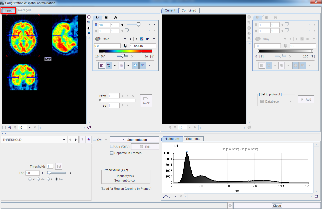
When working with dynamic series, it is recommended to average within an appropriate range in order to obtain an appropriate data set for masking. The range can be specified by the From and To numbers or using the slider handles. When the Average button is activated, the average uptake in the specified frame range is calculated and the result image is shown on the Averaged sub-pane.
Segmentation for Creating a Mask
The next step consists of generating segments which represent tissues of interest. The segments can then be combined into a single mask. Segmentation can be performed on Input series but also on the Averaged images, depending on which tab is selected. The Histogram of the pixel values is updated according to the selected images.
It is recommended to change the color table to Gray, and to enable the overlay Ovr box. Then, select one of the segmentation methods (described below) to specify an inclusion criterion. The pixels which satisfy the criterion are colored in red in the image overlay. Note that overlay updating might be slow when changing a segmentation parameter, depending on the segmentation method. Segmentation performs the actual segmentation and shows the result in the Current tab to the right. While standard segmentations create binary images with 0 (background) and 1 (segment) pixel values, there are clustering approaches which generate multiple segments in a single calculation. These segments are distinguished by increasing integer pixel values. Each Segmentation activation overrides the previous contents in Current.
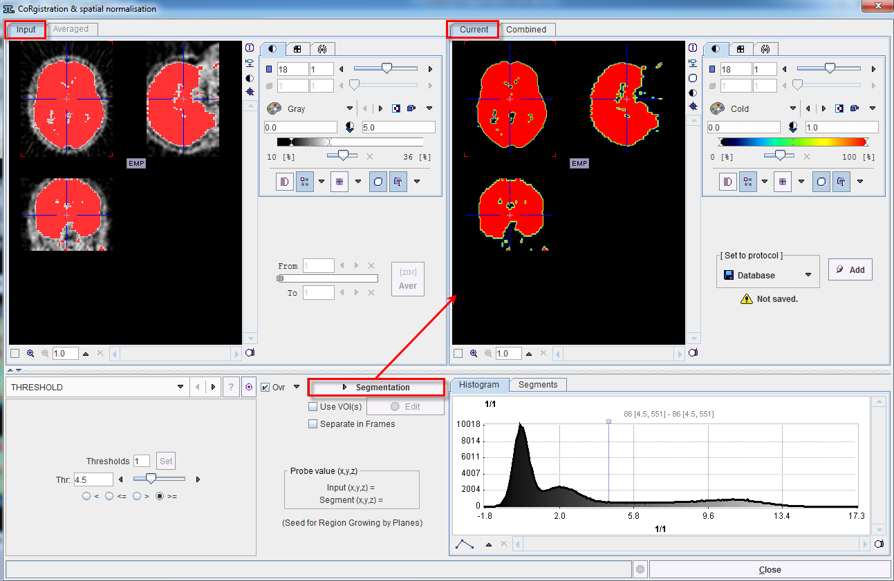
Multiple segments can be combined into a mask. To prepare such a combination, copy promising segments to the Combined tab using the Add button to the right of Set to protocol. By repeated Segmentation and Add operations a list of segments can be built up in the Segments pane as illustrated below.
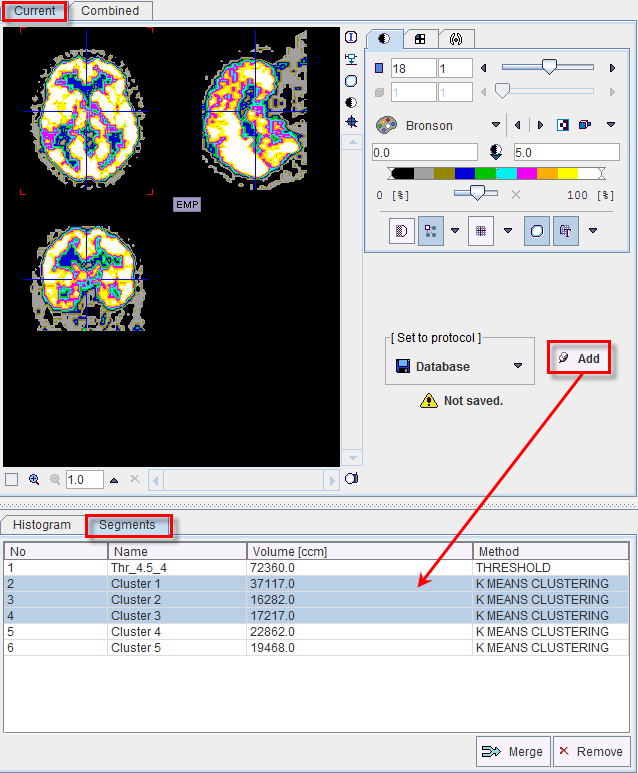
The No entry in the Segments list indicates the number by which a segment is identified in the Combined image, Name provides some descriptive information, Volume its physical volume, and Method identifies the applied segmentation method. Multiple segments in the list can be selected and transformed into a single segment by the Merge button. Hereby, the initially distinct values are replaced by a common value, and the original list entries deleted.
In certain circumstances, the segmentation methods alone may not be sufficient to separate an object form other structures. If this happens, the user can defined a VOI which prevents segmentation from leaving the area of main interest. To do so, the Use VOI(s) box has to be enabled and the Edit VOI button activated. The VOI tools interface appears and allows drawing a VOI. Outline the VOI. Quit the VOI tools with the OK button to confirm the VOI selection. Make sure the overlay Ovr box is enabled. Finally, activate the Segmentation button to perform the actual segmentation within the VOI. The result is shown in the Current tab to the right.
Saving the Mask for Matching Processing
In order to use a generated segment image as a mask in the matching processing it must be saved as a file. Saving can be performed using the Set to protocol pane in any of the supported image formats. Note that automatically the saved file is configured.
Exit the mask interface activating the Close button.
Note that the saved mask is not binary in the case of multiple segments, so that the segments can be recovered. However, during the pixel-wise calculation only the non-zero mask pixels will be processed, while the other pixels are blanked.
2. Load Mask (display definition)
If a mask file already exists, the interactions described above are not necessary and it can be simply configured with the dedicated icon in the reference or input loading pane.

It opens a dialog window as shown below:

The Attached mask file radio button need to be enabled. The drop down arrow  allows switching between different data formats while the Change file or directory
  button can be used to select the mask. The activation of the
 ![]() button next to mask selection allows loading and viewing the mask in a dialog window.
button next to mask selection allows loading and viewing the mask in a dialog window.
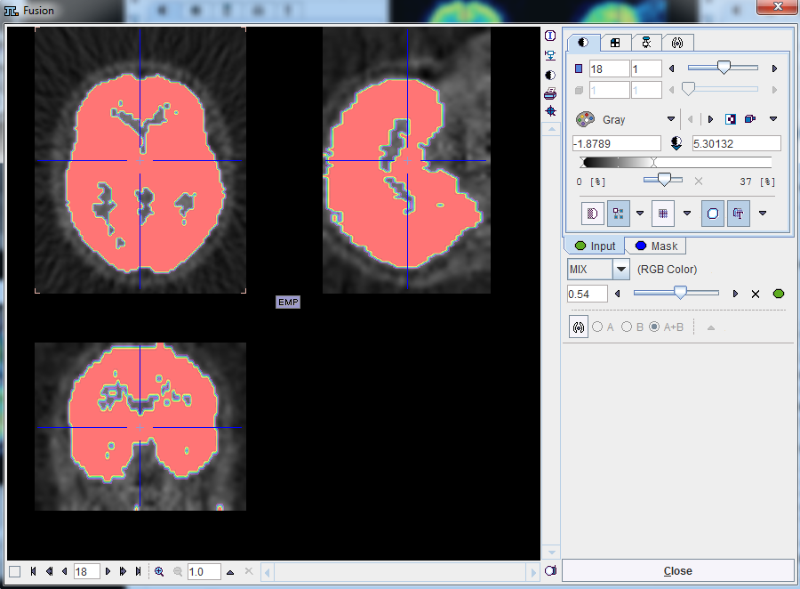
Confirm the selected mask to the protocol activating the OK button in the CoRegistration & spatial normalization dialog window. Upon confirmation the window is closed and the load mask icon changes ![]() .
.
Remove the Mask from the Matching Processing
To remove the mask from the matching processing activate the ![]() in the image Load pane, Initialize/Match page. A dialog window opens. Make sure the Detach mask file (Set empty to protocol) radio button is enabled and confirm the selection with OK.
in the image Load pane, Initialize/Match page. A dialog window opens. Make sure the Detach mask file (Set empty to protocol) radio button is enabled and confirm the selection with OK.
3. Mask definition for Automatic Matching
When the masks are defined in the display, they are immediately set as the corresponding Basic parameters to the automatic matching algorithms. Alternatively, the masks can be defined during the setting of the Basic parameters for the automatic procedures. In the example below, the Reference mask was defined in the display while no mask was defined for the Input image. Note the masks section in the Basic parameters settings: a message alerts that for the Reference image the Mask defined in image display will be used while for the Input image the mask can be loaded and set to the protocol. Note that in this case the mask need to be created and saved beforehand. The mask file corresponding to the Input image will allow restricting the matching algorithm to the meaningful area.
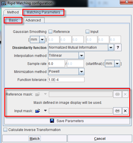
To summarize, there are three potential scenarios: